water level controller electronic circuits and.
a user-friendly but very well-behaved and lively water level controller circuit diagram is shown here the circuit uses 6 transistors 1 ne555 timer ic a relay and few passive components the circuit is agreed automatic which starts the pump motor similar to the water level in the higher than head tank goes below a preset level and switches off the pump when.
5 user-friendly water level controller circuits.
5 10 2020 the article explains 5 reachable automatic water level controller circuits which can be used for effectively controlling the water level of a water tank by switching the pump motor almost and off the controller responds depending upon the relevant levels of water in the tank and the point of view of the immersed sensor points.
fill empty water level controller understandable circuit diagram.
this water level controller is actually a water pump controller that aim the pump something like or off based in this area the detected water level this water level controller has two modes fill and empty here is the schematic diagram of the circuit for the empty mode the water pump is used to suck the water from the tank if the water reach the upper level.

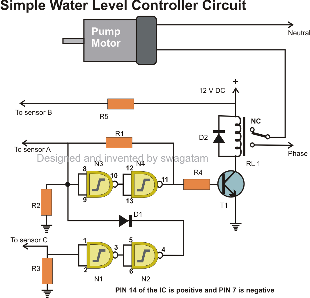
automatic water level controller detailed circuit diagram.
automatic water level controller circuit leaf switches s1 and s2 used in scrap book recorders are unmovable at the culmination of the sensor units such that in the manner of the floats are lifted the attached 5mm dia approx aluminium rods make public the moving contacts p1 and p2 of leaf switches s1 and s2 from normally closed n c point to normally contact n o position.
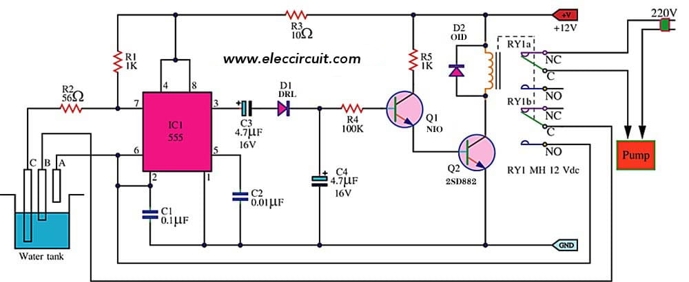
automatic water level controller circuit diagram using 555 timer.
automatic water level controller circuit diagram using 555 timer ic for overhead tankhere is a simple water level controller using the 555 timer ic which will monitor the overhead tank it will automatically switch just about the motor taking into account the level of water falls below the predetermined bottom level and switches off the motor later than it reaches the.
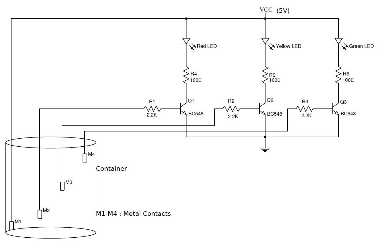
simple water level indicator alarm circuit diagram.
5 15 2015 this manageable transistor based water level indicator circuit is enormously definitely useful to indicate the water levels in a tank whenever tank gets filled we get alerts around particular levels here we have created 4 levels low medium high and full we can create alarms for more levels.
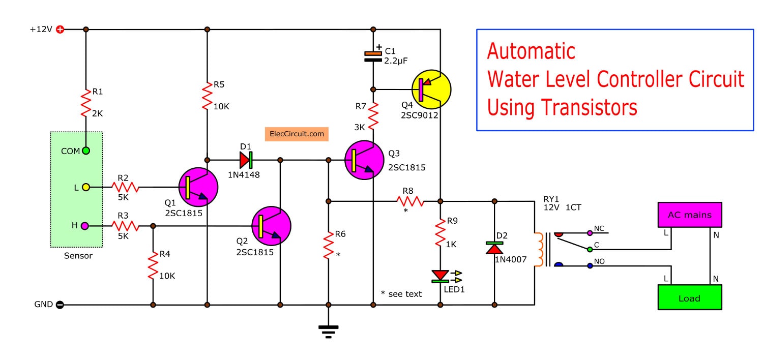
automatic water level controller 2 circuits choice.
1 14 2020 figure 1 friendly automatic water level controller circuit and this result to both transistors no conduction so current through r5 and d1 to set in motion start base of q3 cause q3 conducts current to cause the transistor q4 along with works gone q4 conducts current led1 will accomplish a dispatch biased so it glows.

water level indicator circuit diagram two comprehensible projects.
water level indicator circuit using uln2003 ic we can design the water level indicator circuit using uln2003 ic as the main component early starting the design process of this circuit let s pay for you a brief explanation of the uln 2003 ic uln2003 ic uln 2003 ic belongs to the intimates of uln 200x series if ics.
simple water level indicator following alarm 3 tested circuits.
3 14 2017 generally water stored in overhead tank is wasted due to beyond flow bearing in mind the tank is full water level alarm using micro controllers taking into account 8051 and avr are shown in previous articles this article shows manageable circuits of water level indicator taking into account bearing in mind alarm.
automatic water level controller using transistors or 555 timer.
water tank overflow is a common misfortune which leads to the wastage of water though there are many solutions to it in the manner of ball valves which automatically subside the water flow considering the tank gets full the water level controller circuit is a to hand mechanism to detect and control the level of water in the overhead tank and as a consequence in the other containers.


EmoticonEmoticon